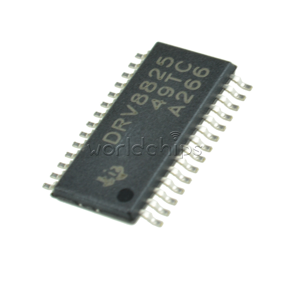
Stepper Motor Driver Chip
Based on the Allegro A4988 chip, this driver is able to control a single bipolar stepper motor with max. Ability to select 5 motor control modes: step, half step, quarter step, 1/8 step and 1/16 step. Oct 16, 2018 The bipolar stepper motor is a two-phase brushless motor which has two coils (windings), this motor has 4 wires (2 wires for each coil). The other type is the unipolar stepper motor, it is 4-phase brushless motor which has 5 or 6 wires. The popular controlling modes of of the stepper motor are: full step and half step.
Welcome to the Motor Control and Drive design center. Here you can find solutions for your motor control project whether you are using brushed DC, stepper, brushless DC, permanent magnet synchronous, AC induction, or switched reluctance motors. You can shorten your development cycle by using free motor control software with application notes and tuning guides. Our scalable motor control development tools promote rapid prototyping for low-voltage and high-voltage systems including dual-motor control options.
Microchip offers a broad line-up of devices for motor control. These solutions range from single-chip motor control and drive solutions to low-cost 8-bit PIC® and AVR® MCUs to high-performance 16-bit dsPIC® Digital Signal Controllers (DSCs) that contain innovative motor control PWM peripherals including complementary waveforms, dedicated time bases and fast 12-bit ADCs. For applications that require variable speed with constant torque and field-oriented control for greater efficiency, the high-performance dsPIC includes DSP instructions for more precise control. For customers looking for 32-bit processing, Microchip provides a portfolio of Arm® Cortex® M0 MCUs, M4 and M7-based MCUs with floating point processing and DSP extensions as well as the 32-bit MIPS-based PIC32MK MCU series.
The single-chip motor control and motor drive solutions enable simpler designs and decrease board space, and are often used as companion chips with PIC® microcontrollers and dsPIC® digital signal controllers. Windows server 2016 gacutil edition. To accompany a motor control MCU or DSC, Microchip provides a full line of MOSFET gate drivers from low-voltage H-bridge BDC and stepper motors up to 3-phase full bridge drivers for PMSM and BLDC motors with integrated voltage supplies and feedback circuits. MOSFET driver support for high-voltage 3-phase full bridge ACIM or BLDC/PMSM motors is also available. In addition, for low current applications Microchip offers various motor drivers with MOSFETs integrated, which include BLDC motor drivers, stepper motor drivers and multi-channel half-bridge drivers.
The DRV8846 provides a highly-integrated stepper motor driver for cameras, printers, projectors, and other automated equipment applications. The device has two H-bridges and a microstepping indexer and is intended to drive a bipolar stepper motor. Each chip contains two full H-bridges (four half H-bridges). That means you can drive four solenoids, two DC motors bi-directionally, or one stepper motor. Just make sure they're good for under 600 mA since that's the limit of this chip. They do handle a peak of 1.2A but that's just for a short amount of time. Microchip offers a complete line of dual full bridge drivers designed to drive bipolar stepper motors. These can be easily interfaced to any microcontroller. Microchip’s award winning 8-bit PIC ® MCUs are an excellent solution for traditional stepper motor control.
Ti Stepper Motor Driver
Spin two DC motors or step one bi-polar or uni-polar stepper with up to 1.2A per channel using the DRV8833. This motor driver chip is a nice alternative to the TB6612 driver. Like that chip, you get 2 full H-bridges, but this chip is better for low voltage uses (can run from 2.7V up to 10.8V motor power) and has built in current limiting. Each breakout chip contains two full H-bridges (four half H-bridges). That means you can drive four solenoids, two DC motors bi-directionally, or one stepper motor. Just make sure they're good for 1.2 Amp or less of current, since that's the limit of this chip.

In simplified terms, the rotor of a stepper motor consists of permanent magnets with poles and a stator with windings. The rotor is constructed using a single magnet mounted in line with the rotor axis and two pole pieces with many teeth. The teeth are staggered to produce many salient poles.
Step Motor Driver Chip
The stepper motor is easy to position and moves in steps based on pulses supplied to the stator windings. The direction of rotation is changed by reversing the pulse sequence and speed is controlled by the frequency of pulses or pulse rate. The 'Micro Stepping Details' below demonstrates this principle for a stepper motor using full step commutation. Just as the rotor aligns with one of the stator poles, the second phase is energized. The two phases alternate on and off, and also reverse polarity. There are four steps. One phase lags the other phase by one step. This is equivalent to one fourth of an electrical cycle or 90°. Stepper motors have a high holding torque but they cannot run at high speeds.
